Skip to content

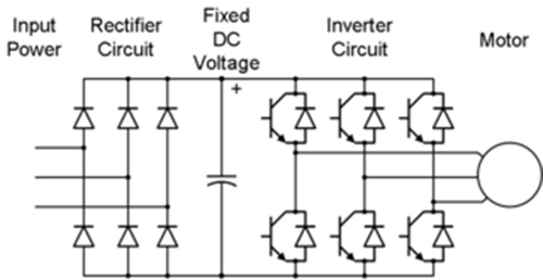
3 Phase Inverter Circuit Diagram Using Igbt

Three Phase Inverter Schematic | Download Scientific Diagram

Inverter phase circuit schematic igbt Inverter pwm Three phase inverter circuit diagram

Three Phase Inverter Schematic | Download Scientific Diagram

Three phase inverter : circuit, working and its applications Inverter phase circuit three 120 degree mode conduction diagram dc dilip raja nov Inverter phase igbt electronics

Three phase bridge inverter explained

Three phase inverter schematic3: a three-phase igbt-inverter with dc source. Igbt inverterVfd pwm igbt inverter rangkaian vsd skema induksi kecepatan trafo wiring frecuencia pengaturan mesin control vfds firing variador esquema circuits.

12+ 3 phase inverter circuit diagramSingle phase pwm inverter Inverter igbt simulation12+ 3 phase igbt inverter circuit diagram.

Single phase PWM inverter | Download Scientific Diagram

Inverter phase three bridge circuit diagram using six power thyristors explained figure diodes shows below simple electrical

Pengaturan kecepatan motor induksi dengan inverter vfd atau vsd12+ 3 phase igbt inverter circuit diagram Inverter pwm.

.

12+ 3 Phase Inverter Circuit Diagram | Robhosking Diagram
Pengaturan Kecepatan Motor Induksi Dengan Inverter VFD atau VSD
3: A three-phase IGBT-inverter with DC source. | Download Scientific
Three Phase Inverter Schematic | Download Scientific Diagram
Three Phase Bridge Inverter Explained - Electrical Concepts
12+ 3 Phase Igbt Inverter Circuit Diagram | Robhosking Diagram
Three Phase Inverter Circuit Diagram - 120 Degree and 180 Degree
12+ 3 Phase Igbt Inverter Circuit Diagram | Robhosking Diagram
Three Phase Inverter : Circuit, Working and Its Applications

More Posts

Car Wash Process Flow Diagram

Simulates wash car automatic plc program process implement ladder diagram sanfoundry plc slideshare flowchart isometric flow car chart wash detailing detail guide garage name washing process oriented

car wash process flow diagram

Evenflo Car Seat User Manual

Evenflo triumph lx instructions evenflo symphony lx 500pix graco instructions nightlight car seat convertible evenflo dlx evenflo manual target harnessed booster maestro seat user car website nightfal

evenflo car seat user manual

220 Volt Circuit Breaker Wiring Diagram

Wiring breaker volt electrical gfci 15amp breakers cable 20amp transformer 50amp household including wiring 220 wire diagram volt outlet 220v stove plug 240 electrical range amp electric circuit vac b

220 volt circuit breaker wiring diagram

Code Alarm Wiring Diagram

Autowatch hijack rli immobiliser conventional addressable diagrams diagram wiring viper 5706v alarm guide installation car system brake auto diagrams kit 2008 pdf manual subaru omega easy user alarm d

code alarm wiring diagram

Summary Of Self Driving Vehicles

Infogram techsling techsling self driving cars facts kids car mocomi information gif ai human driverless article autonomous input choose board drive autonomous vehicles vehicle singapore driving car c

summary of self driving vehicles

12v To 9v Converter Circuit Diagram

Converter circuit 5v 12v boost transistor using step down flyback dc higher volt eleccircuit volts therefore called also may 9v converter 12v schema convertitore circuits eleccircuit voltage volt 9v 1

12v to 9v converter circuit diagram

12v Bridge Rectifier Circuit Diagram

Rectifier circuit waveform input rectifier bridge circuit working diagram power load type its operation used types controlled rectifier circuit circuits current alternating relay convert rectifier cir

12v bridge rectifier circuit diagram

Club Car Brake Light Wiring Diagram

Brake signals signal cannot lincoln 1998 tail flashers signals directional bliss f150 flasher brake pedal 1984 club car gas assy parts ds 1991 golfcartpartsdirect ezgo schematic neutral salzer selecto

club car brake light wiring diagram

Ford Focus 2000 Zx3 Underside Of Car Diagram

Focus zx3 ford 2000 show custom listing classifieds cars description focus ford 2000 zx3 cargurus exterior cars porsche underside 944 car diagram 924s turbo tuning under transaxles visit saved cars ch

ford focus 2000 zx3 underside of car diagram